A quick review of serial communication
by yaobin.wen
(Updated on 2023-04-04)
1. What is serial communication?
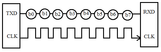
Serial communication is a communication method that uses one or two transmission lines to send and receive data, one bit at a time.
The following figure from [4] shows serial communication:
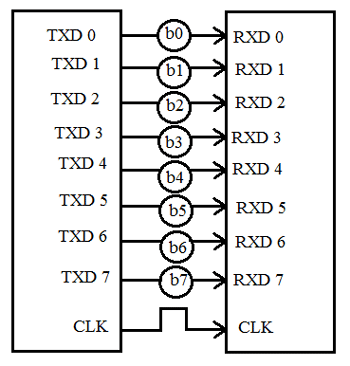
In contrast, parallel communication transfers multiple bits at the same time. They usually require buses of data - transmitting across eight, sixteen, or more wires.
The following figure from [4] shows parallel communication:
The two ways of communication can be compared as follows:
| Parameter | Serial Communication | Parallel Communication |
|---|---|---|
| Transmission | One bit at one clock pulse | A chunk of data at a time |
| Number of lines | 1 | N lines for transmitting N bits |
| Communication speed | low | fast |
| Cost | Low | High |
| Situation | Preferred for long distance | Preferred for short distance |
2. RX and TX
A serial communication device should have two serial pins:
RX: the receiver.TX: the transmitter (i.e., sender).
The following figure from [5] shows how RX and TX pins are wired:
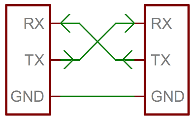
When sending data, the sender sets the signal on the wire to the corresponding bit state, and the receiver samples the signal on the wire to get the bit state. Therefore, it’s important that the sender and the receiver work in the same frequency (i.e., baud rate, see below). Otherwise, the receiver will just reads wrong data.
There are two common ways to guarantee the two devices work in the same frequency: using a clock (i.e., synchronous) or not using a clock (i.e., asynchronous).
3. Serial communication: synchronous vs asynchronous
Serial communication protocols can be sorted into two groups: synchronous and asynchronous.
In synchronous transmission:
- The sender and the receiver share the same clock signal. This is usually done by accompanying the data lines with at least one additional clock line between the two devices.
- The receiver only samples the data wire when the clock signal is at a specific state (i.e., rising or falling). See [6] “A Synchronous Solution”.
- Each character or byte does not have to start with a start bit or end with a stop bit, so the transfer rate is higher compared with the asynchronous transmission.
- Requires master/slave configuration (because the master device needs to provide the clock signal to all the receivers).
- Cost is higher because it requires at least two wires (data wire and clock wire).
In asynchronous transmission:
- The sender and the receiver do not use a clock to synchronize data.
- Data is sent in character or byte, so the speed is low.
- Each character or byte starts with a start bit and ends with a stop bit in order to tell the receiver where data start and end.
- There is a time delay between the communication of two bytes.
- The sender and the receiver may work at different clock frequencies.
- The timing errors can accumulate on the sender and the receiver, so synchronization bits can be inserted into the data flow in order to correct the timing errors.
- Cost is lower because it requires only one wire.
4. Serial communication standards
RS-232C/RS-422A/RS-485 are EIA (Electronic Industries Association) communication standards (where “RS” means “Recommended Standard”).
| Standard | Alias | Purpose of signal lines | Timing of signal lines | Connectors |
|---|---|---|---|---|
| RS-232C | EIA-232 | Defined | Defined | Defined (D-sub 25-pin or D-sub 9-pin connectors) |
| RS-422A | EIA-422A | Defined | Defined | Not defined (adopt D-sub 25-pin and D-sub 9-pin) |
| RS-485 | EIA-485 | Defined | Defined | Not defined (adopt D-sub 25-pin and D-sub 9-pin) |
Other notes:
- RS-422A fixes problems in RS-232C such as a short transmission distance and a slow transmission speed.
- RS-485 fixes the problem of few connected devices in RS-422A.
| Parameter | RS-232C | RS-422A | RS-485 |
|---|---|---|---|
| Transmission mode | Simplex | Multi-point simplex | Multi-point multiplex |
| Max. connected devices | 1 driver 1 receiver |
1 driver 10 receivers |
32 drivers 32 receivers |
| Max. transmission rate | 20Kbps | 10Mbps | 10Mbps |
| Max. cable length | 15m | 1200m | 1200m |
| Operation mode | Single-ended (unbalanced type) |
Differential (balanced type) |
Differential (balanced type) |
| Features | Short distance Full-duplex 1:1 connection |
Long distance Full-duplex, half-duplex 1:N connection |
Long distance Full-duplex, half-duplex N:N connection |
5. Signal assignments and connectors
The figure from [1] describes the D-sub 9-pin signal assignments and signal lines that are defined in RS-232C.
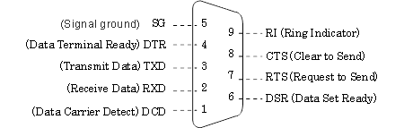
| Pin No. | Signal Name | Description |
|---|---|---|
| 1 | DCD | Data Carrier Detect |
| 2 | RxD | Received Data |
| 3 | TxD | Transmitted Data |
| 4 | DTR | Data Terminal Ready |
| 5 | SG | Signal Ground |
| 6 | DSR | Data Set Ready |
| 7 | RTS | Request To Send |
| 8 | CTS | Clear To Send |
| 9 | RI | Ring Indicator |
| CASE | FG | Frame Ground |
6. Equipment types & connection methods
There are two types of equipment:
- Data communication equipment (DCE): Equipment that passively operates such as modems, printers, and plotters.
- Data terminal equipment (DTE): Equipment that actively operates such as computers.
When connecting two devices of different types together, one needs to use a straight through cable. When connecting two devices of the same type together, one needs to use a crossover cable:
| Device 1 | Device 2 | Connection |
|---|---|---|
| DCE | DCE | crossover |
| DCE | DTE | straight through |
| DTE | DCE | straight through |
| DTE | DTE | crossover |
7. Transmission modes
There are three transmission modes:
- Simplex
- Half Duplex
- Full Duplex
Suppose we have two devices A and B that are connected via a serial cable, then:
- Simplex: Only
Acan send data toBbutBcannot send toA.- Examples: radio, television, printer.
- Half Duplex:
AandBcan send data to each other but not at the same time. When one is sending data, the other one can only receive.- Examples: Walkie-Talkie
- Full Duplex:
AandBcan send and receive data at the same time.- Examples: Telephone
8. Baud rate
Baud rate is the rate at which information is transferred. Its unit is bits per second (bps). The user needs to set the baud rate on both the sender and the receiver.
9. Parity bit
Parity bit is used to find errors in data transfer. Three different configurations are available:
- even parity check (EVEN)
- odd parity check (ODD)
- no parity check (NONE)
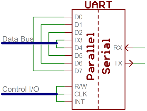
10. Universal Asynchronous Receiver/Transmitter (UART)
A universal asynchronous receiver/transmitter (UART) is a block of circuitry that acts as an intermediary between parallel and serial interfaces. On one end of the UART is a bus of eight-or-so data lines (plus some control pins), on the other is the two serial wires - RX and TX. The figure from [5] shows this:
11. Serial Peripheral Interface (SPI)
Serial peripheral interface (SPI) is a synchronous solution for serial communication. The following figure from [6] shows the components in SPI:
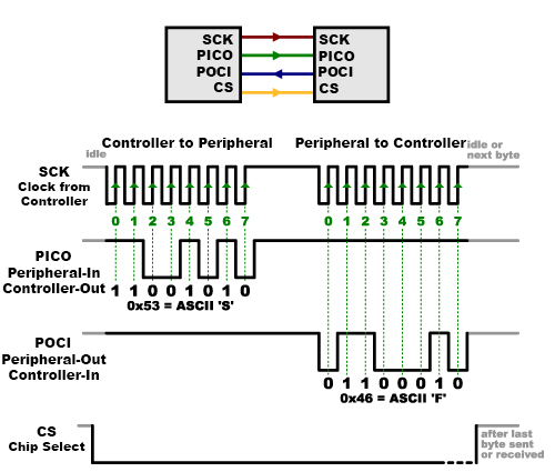
- Controller: The device that generates the clock signals. There is always only one controller.
- Old name: master
- Peripheral: The device that acts based on the received clock signals. There can be one or multiple peripherals.
- Old name: slave
- CLK/SCK: The clock signal. (
SCKmeans “Serial Clock”.) - PICO: “Peripheral In / Controller Out”, the data line for the controller to send data to the peripheral.
- POCI: “Peripheral Out / Controller In”, the data line for the peripheral to send data to the controller.
- CS: “Chip Select”, the line that tells the peripheral that it is being selected for communication.
- Usually “active low”, meaning when it’s held high, the peripheral is disconnected from the communication bus; when it’s held low, the peripheral is connected to the communication bus.
Because only the controller can generate clock signals, when the controller needs to receive data from the peripheral, the controller needs to “expect” that, i.e., when sending the command, the controller needs to know in prior whether the command will return something or not. “In practice this isn’t a problem, as SPI is generally used to talk to sensors that have a very specific command structure.” [6]
References
- [1] Serial communication Basic Knowledge -RS-232C/RS-422/RS-485
- [2] What is Serial Communication? How does it work?
- [3] The difference between straight through cable, crossover, and rollover cables
- [4] RS232 Serial Communication Protocol: Basics, Working & Specifications
- [5] SparkFun Electronics: Serial Communication
- [6] SparkFun Electronics: Serial Peripheral Interface (SPI)